Build your own EX-CommandStation – A DIY entry-level DCC Controller based on the DCC-EX Project.
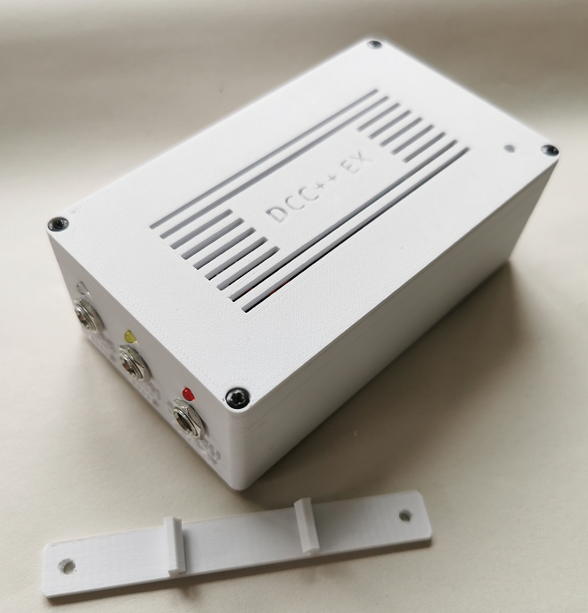
3D Printable files are available for the Mk1 version of the Commandstation and may be downloaded from the Thingiverse Website at ‘Railsnail’ DCC-EX (Mk1) Enclosure by Railsnail – Thingiverse

This version is WiFi connected meaning that your railway layout may be controlled wirelessly using the WiThrottle protocol via WiFi, or indirectly through the JMRI computer that has WiFi and its own WiThrottle Server.
Android App DCCpp CAB can connect directly and sends native <DCC++> commands.
Similarly, the Engine Driver App can connect directly to the CommandStation as it natively supports the WiThrottle protocol.
In keeping with the DCC-EX current design philosophy, the microcontroller board used in this design is the Arduino Mega2560 (or clone).
DCC signals to the MAIN or PROG tracks are derived from an Arduino Motor Shield that simply piggy-backs off the Mega2560 microcontroller.
The whole CommandStation is powered by one DC power supply (+15V DC) fitted with a 5.5mm x 2.1mm DC plug. A buck converter module (LM2596) reduces the input voltage to 7.5V DC to power the Arduino Mega2560.
Output to the MAIN and PROG tracks is via 5.5mm x 2.5mm DC sockets. The use of 2.5mm centre pins should ensure that the DC Power Supply cannot be connected to these sockets accidentally, causing damage to the CommandStation.
DCC commands input to the CommandStation is via an ESP8266 WiFi microchip which is plugged into an ESP01 Serial Adapter module.
Finally, the CommandStation is housed in a suitable enclosure. In this example, a 3D printed PLA enclosure was designed and printed specifically for this project, although any enclosure (116mm long x 68mm wide x 40mm high) or larger should suffice.
3D Printable files are available for the Mk1 version of the Commandstation and may be downloaded from the Thingiverse Website at ‘Railsnail’ DCC-EX (Mk1) Enclosure by Railsnail – Thingiverse
Parts List
- 1x Arduino Mega 2560
- 1x Arduino Motor Shield
- 1x ESP8266 ESP-01
- 1x ESP8266 ESP-01 Serial Adapter
- 1x LM2596 Buck Converter Module
- 1x 15V DC 3A Power Supply (3A recommended) – With 5.5mm 2.1mm plug (centre pin positive). *
- 1x 3mm Pre-wired Red LED (incorporating 1.2kOhm series resistor)
- 1x 3mm Pre-wired Yellow LED (incorporating 1.2kOhm series resistor)
- 1x 3mm Pre-wired Blue LED (incorporating 1.2kOhm series resistor)
- 2x 470 Ohm 1/4W resistors (470 Ohm suggested, but actual value dependant on LED forward Voltage/Current rating)
- 5x Mini Micro JST-PH 2.0 JST – 2 Pin Male Plug Connector Cable. Pre-wired/Crimped
- 5x Mini Micro JST-PH 2.0 JST – 2 Pin Female Plug Connector Cable. Pre-wired/Crimped
- 1x 5.5mm 2.1mm Female DC Power Socket (Power In)
- 1x 5.5mm 2.1mm Male DC Power Plug (Power In)
- 2x 5.5mm 2.5mm Female DC Power Socket (Main/Prog)
- 2x 5.5mm 2.5mm Male DC Power Plug (Main/Prog)
- 2x 2 way 2.54mm single right-angle PCB connector
- 30AWG multi-strand wire – Red, Blue, Yellow and Green
- Heat-Shrink tubing – various to suit
- Enclosure – 3D Printed (Or a proprietary plastic enclosure of suitable size (116mm long x 68mm wide x 40mm high)
- 4x Stick on feet – For enclosure
- 4x Self-tapping Panhead screws – M2.3 x 8 To secure enclosure’s lid
- Double-sided sticky pads
* DC Power supplies with plug size different to 5.5mm 2.1mm will require plug removal and replacement ensuring the centre pin of the replacement is wired to DC positive!
Interconnecting Cables/LED Connections
Where possible, readily sourced pre-made (JST-PH 2.0) cables and 3mm LED assemblies have been used as this reduces soldering/crimping of connectors increasing reliability and reducing soldering to a minimum. At the time of writing, cables and pre-wired LEDs are available from Amazon UK.
Using these cable types allows the CommandStation’s external sockets (Power, Main and Prog Track) to be conveniently connected/disconnected to/from the internal modules (Mega2560, Arduino Motor Shield and LM2596 Buck converter) allowing for easier servicing and build.
Careful selection of male/female JST-PH JST connector combinations should avoid incorrect interconnections between the modules and DC sockets.
Pre-wired 3mm LED assemblies have also been used that incorporate 1.2k ohm series resistors as supplied. (The resistors are not shown on the assembly diagram below).
Two additional series resistors, (R1 and R2), connected in series with the LEDs that indicate Main and Prog Track power are included due to the higher voltages output on these sockets. These resistors are soldered directly onto the DC (Main and Prog Track) socket terminals and covered in heat-shrink tubing. (See the construction directions below). Suggested values of 470 ohms may change according to the max forward current value of LEDs used.
Note that the wire lengths shown below are given as a guide in the construction notes assume that the 3D printed case dimensions (116mm long x 68mm wide x 40mm high) and module locations have been followed.
Larger enclosures/Differing layouts will require different wire lengths to those shown below.
Construction
Solder Mega2560 Power Supply Wire
The 3D printable enclosure design downloadable from the Thingiverse Website at ‘Railsnail’ DCC-EX (Mk1) Enclosure by Railsnail – Thingiverse can house a genuine Arduino Mega2560 module OR a Mega2560 clone. (Locations of the USB and Power Supply Socket differ slightly between the two versions). The 3D case design can accommodate both variants with optional printable port covers hiding any gaps caused by the differences.

(Pre-wired JST-PH 2.0 Male/Female Power connectors are used in this build therefore crimps are not required, and red/black wires can be cut to the required length).
CBL1 – Take a female JST-PH 2.0 part. Cut wires to a length of 120mm approx. and strip, tin and solder the red and black wires to the +ve/-ve pads/vias on the underside of the Mega DC socket.
(The picture shows the Mega2560 Power Supply Socket removed. Just solder the red and black wires to the corresponding pads on the underside of the board).
LM2596 Buck Converter Module Wiring
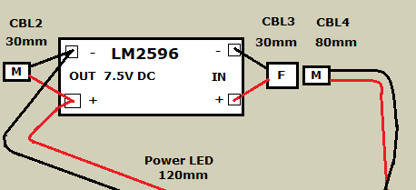
CBL-2 – Cut the wires to a male JST-PH 2.0 part to 30mm length. Strip, tin and solder the red and black wires to the Buck converter’s output terminals. Observe DC polarity. (See diagram).
LED1 ‘Red Power LED’ – Cut the wires on the RED 3mm LED/Resistor assembly to 120mm length. Strip, tin and solder the red and black wires to the Buck converter’s output terminals. Observe DC polarity.
Attach Power and Data ‘flying’ leads to the ESP-01 adapter connector:-
RX/TX Data – Cut approximately 30mm of green and yellow 30AWG wire. Solder the green wire to the ESP-01 Adapter Module TX connector and the yellow wire to RX. Insulate connections with heat-shrink tubing. (see above photo)

Solder the other ends of these wires to a two-way 2.54mm single right-angle PCB connector observing orientation. Insulate with heat-shrink tubing.
Power – Cut approximately 60mm of red and blue 30AWG wire.
Solder the red wire to the ESP-01 VCC adapter connector.
Solder the blue wire to GND.
Insulate connections with heat-shrink tubing. (see photo – right)
Solder the other ends of these wires to a two-way 2.54mm single right-angle PCB connector observing orientation.
Insulate with heat-shrink tubing.
POWER, MAIN Track, PROG Track Sockets and LED Indicators
Cut the following to length before soldering to the DC connectors:-
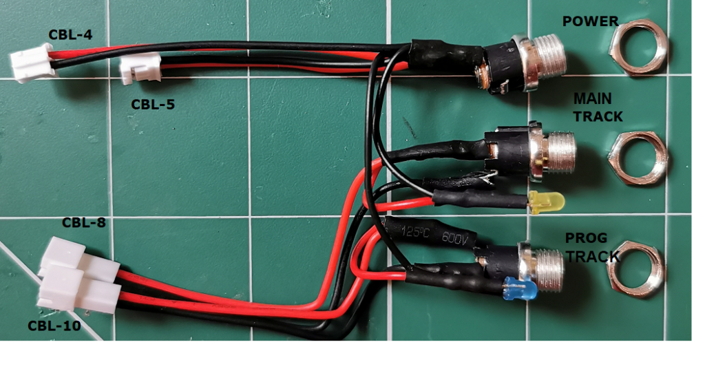
- CBL-4 – (To LM2596 Power In) Cut the wires on a male JST-PH 2.0 part to approx. 80mm length.
- CBL-5 – (To Motor Shield Power In) Cut the wire on a female JST-PH 2.0 part to approx. 100mm length.
- CBL-6 – (To Power Connector) Cut the wires on a male JST-PH 2.0 part to approx. 60mm length.
- CBL-7 – (To Motor shield B terminals) Cut the wires on a male JST-PH 2.0 part to approx. 65mm length.
- CBL-8 – (To MAIN Track DC Socket) Cut the wires on a female JST-PH 2.0 part to approx. 95mm length.
- CBL-9 – (To Motor shield A terminals) Cut the wires on a male JST-PH 2.0 part to approx. 65mm length.
- CBL-10 – (To PROG Track DC Socket) Cut the wires on a female JST-PH 2.0 part to approx. 95mm length.
- LED2 – (Yellow MAIN Track Power On Indicator) – Cut the wires to a length of approx. 50mm
- LED3 – (Blue PROG Track Power On Indicator) – Cut the wires to a length of approx. 65mm
With reference to the following diagram and above picture, solder the cables/LEDs to the 3 DC Connectors carefully checking polarity and DC Connector pin sizes. DC Power Socket Centre pins (tip) is positive.
The (DC) POWER socket has a 2.1mm dia centre pin size while the MAIN Track and PROG Track Sockets centre pin size is 2.5mm dia. Do not mix these.

CommandStation Assembly
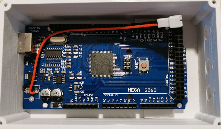
Check thoroughly for the polarity of all connections. A little time spent here may save smoke and problems later!
Attach double-sided sticky pads to the underside of the Arduino Mega2560, then locate it into the 3D printed enclosure, ensuring the PCB locating holes line up with the enclosures stand-offs and the module is firmly attached to the enclosure.
When deciding on the location of the sticky pads, make sure that there is sufficient airflow into the enclosure through the bottom grilles and around the PCB.
The sticky pads should retain the Mega2560 securely in position but will allow the board to be removed should the need arise.
Arduino Motor Shield

Cut the unused Header Pins, (20 in total marked in red on the picture), located on the top side of the Arduino Motor Shield using strong side cutters.
Cutting these will reduce the possibility of the LM2596 Buck Converter components (mounted above the motor shield) coming into contact with these pins.
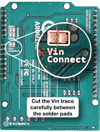

WARNING!
As stated in the EX-CommandStation Official Build Documentation.
The Vin trace must be cut on the bottom side of the Arduino Motor Shield.
Failure to do this will result in catastrophic damage to the Mega2560/Bluetooth Module/Buck Converter.
Make the cut using a craft knife or similar. Then check that the two pads shown ARE ISOLATED with an ohm-meter
Take the cables CBL-5, CBL-7 and CBL-9 and insert the stripped ends into the (Green) Arduino Motor Shield screw connector and tighten the screws. (see above Connection Diagram for connection orientation details).
Check again that the Vin trace has been cut on the reverse of the Arduino Motor Shield. (See above warning).

Attach the Arduino Motor Shield to the Arduino Mega2560 ensuring all the inter-connecting pins are correctly aligned and not bent (see picture). Press the module firmly onto the Mega2560 connectors.
Attach double-sided sticky pads to the underside of the ESP-01 Adapter/Attached ESP-01 and stick these modules onto the top of the Mega2560 PCB at the position shown ensuring the Mega RESET switch is not pressed down by modules.
(Note that the picture shows the Bluetooth Version, however, the ESP01 attaches to the Mega2560 board at the same location).
Connect the two flying leads:-
- The Power flying lead connects to Arduino sockets marked +5V (red) and GND (blue)
- The Data flying lead connects to Arduino sockets marked TX0 (yellow) and RX0 (green) as shown in the picture.
Double-check the power leads are aligned correctly else damage will occur!
Attach a double-sided sticky pad to the underside of the LM2596 Buck converter, locate it onto the underside of the 3D printed enclosure lid ensuring the PCB location holes fit onto the moulded stand-offs. The lid should be orientated with the ‘Reset’ hole as shown.
Make sure it is securely attached to the enclosure lid and the orientation is as shown below (i.e. Input terminal on the right, output left). A dab of glue on each stand-off should ensure the converter is securely attached and will not drop off the lid.
IMPORTANT. Rotate the trimmer potentiometer located on the Buck converter fully anti-clockwise. (This will set the converter output voltage to a minimum thus avoiding possible over-voltage damage later).
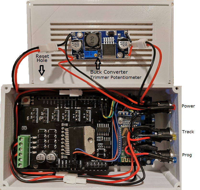
Insert the DC sockets and LEDs into their enclosure locations as shown.
In the above photo, the POWER socket (with 2.1mm centre pin) is located top right as shown (adjacent to red LED).
The centre socket is the MAIN track output (with a 2.5mm centre pin). The LED indicator is yellow.
The last socket is PROG track output (also with a 2.5mm centre pin) with a blue LED indicator.
Secure the sockets with the supplied nuts and apply a small blob of glue around each LED on the inside of the enclosure to prevent the LEDs from working loose.
Set The Buck Converter Output Voltage
Disconnect all JST-PH 2.0 connectors (if connected).
WARNING. Rotate the trimmer potentiometer (the blue component in pictures above) located on the Buck converter full anti-clockwise. (This will set the converter output voltage to a minimum value thus avoiding possible over-voltage damage later).
Connect the 15V DC Power Supply to the DC POWER socket and connect it to mains power.
Slowly rotate the Buck converter trimmer potentiometer in a clockwise direction while monitoring the output of the converter with a voltmeter until the voltmeter reads 7.5V +/- 0.2V
The POWER LED should illuminate red.
Disconnect the 15V power supply and connect all the JST-PH 2.0 plugs and sockets as shown in the above connection diagram/photos.
Inspect soldered connections to ensure correct polarity. Also, ensure that the JST-PH 2.0 connectors have not been supplied with any incorrectly terminated sockets.
It is worth taking some time checking everything at this point, as it may result in less smoke and damage later!
Compile and Upload the EX-CommandStation Arduino Sketch
Having assembled the CommandStation we can install the software then return here to carry out some simple tests.
Quick Test
We can now perform a quick test:-
- Power the EX-CommandStation from the mains DC Power Supply, the LED power indicator (Red) should illuminate.
- Connect a USB cable from your computer to the USB port
- From the Arduino Serial Monitor, set the Baud-rate to 115200 and select both NL and CR
- In the Serial Monitor, enter the command <1> and click Send
- The Main/Prog Track LEDs on the CommandStation should illuminate
- Enter the command <0> and click Send
- The Main/Prog Track LEDs should be turn off
Finally…
The final stage of the CommandStation build is to attach the lid using M2.3 x 8 Panhead self-tapping screws.
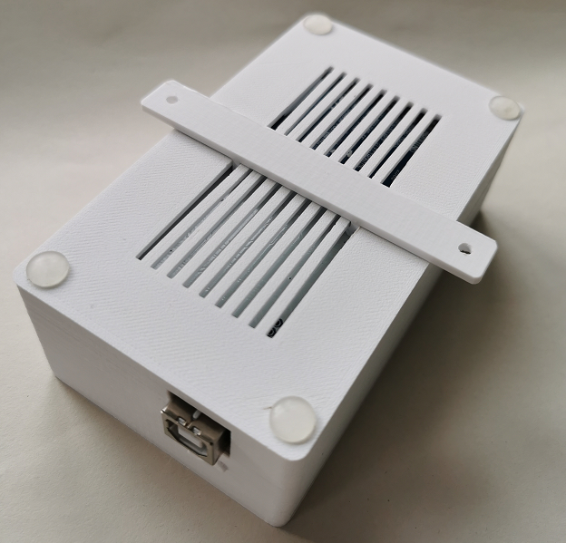
Attach 4 sticky feet to the base of the enclosure.
Solder your MAIN and PROGRAM track feeder cables to 5.5mm x 2.5mm DC Plugs
OR
(Optionally). Make two PROGRAM and MAIN Track ‘pigtail’ cables using 5.5mm x 2.5mm DC Plugs, 100mm cable and terminate these with click release connectors so that your MAIN and PROGRAM Track cabling may be easily and quickly connected. (See picture below)
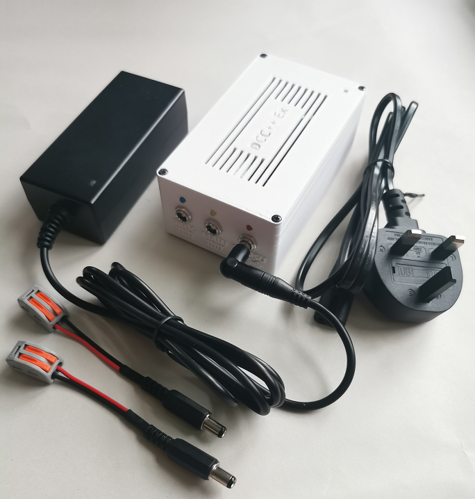
Optional Fixing Bracket
An optional fixing bracket may be attached to the underside of the enclosure. It simply clicks into place with small tabs that fit between the vents. Once the bracket is clicked into place it may be screwed to a surface with the 4 sticky feet and the bracket acting as spacers thus allowing air to circulate through the vents.