There are many types of 3D printing technologies, but probably the most accessible for Railway Modellers, in terms of affordability, are Fused Deposition Modelling (FDM) and Stereolithography (SLA) printers.
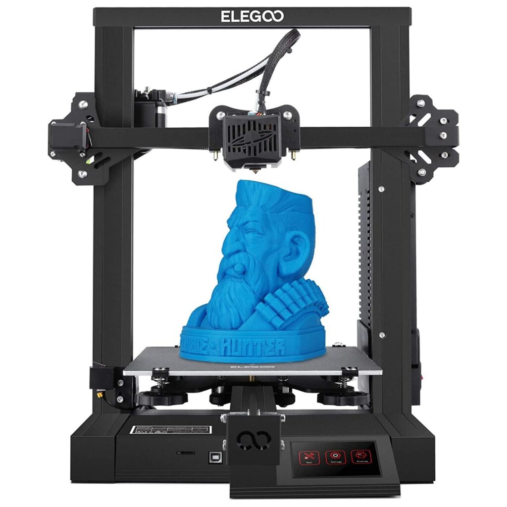
In very basic terms, FDM printers extrude plastic through a tiny nozzle in order to build a model layer by layer. SLA printers use a light source to cure a photosensitive resin to produce solid layers and, eventually, whole parts.
Luckily, for the modelling community, the prices of these two technologies have tumbled with ever cheaper and relatively sophisticated printers being available meaning that many model items may be homemade with sufficient imagination and skill.
Heljan Class 128 Repair
So the issue I faced was to repair a Heljan OO Class 128 Locomotive with two broken ‘suspension bridge’ components using my newly acquired FDM printer, an Elegoo Neptune 2.
I had purchased the loco used, and I guess it had been dropped or thrown about in transit resulting in the breakages! Replacement parts are available from a UK agent, however, I saw this as an opportunity to attempt to make my own.
For those unfamiliar with the ‘suspension bridge’ parts, they are two plastic parts, (one for each bogie), that attach the two bogies to the chassis casting allowing them to move horizontally and vertically.
My options were to buy replacement parts or attempt to 3D print my own. So, I decided to do both meaning that if I failed in my component printing experiment, then I could use the OEM replacements at a later date.
As I had the broken parts and they could be measured with my digital callipers, I proceeded to attempt to create a drawing of them in Sketchup Free. A web-based version of the full Sketchup CAD software allowing basic modelling functions.
As I was new to Sketchup, much forum searching/trial and error ensued. Luckily there are many resources especially on Youtube that allow a complete beginner like myself to get started.
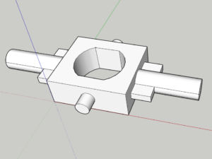
So, after some time, I arrived at my model. Not as rounded and aesthetic as the OEM part, but hopefully all the critical parts/dimensions were correct and it would do the job.
It looked right, but could I print it and would it work?
I downloaded the STL file (from my completed Sketchup model) imported it into Cura (software that takes an STL file and creates an output file used by the FDM printer to create a finished model), and all looked good.
I decided to print it with 100% infill using the ‘Normal’ profile.
(For those interested, I printed it with white eSun brand PLA+. Extruder temperature 210 deg C, plate temp 50 deg C. I reduced the print speed to 25mm per sec and printed with ‘tree’ supports for the overhanging parts of the component. Other parameters were left at default settings).
Cura calculated a print time of 10 minutes, so I wouldn’t have to wait very long to see the finished article.
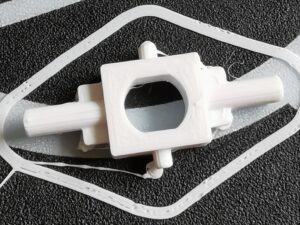
Sure enough, around 10 minutes later I had this…
Pictured just as printed, still attached to the build plate and with supports still attached.
After detaching it and trimming the supports with a craft knife, it appeared to resemble the OEM part and checking with my callipers, all appeared to be okay with dimensions. But as they say, the proof is in the pudding.
I checked that the little pivot parts fitted nicely into the top bogie clip (see the pivot point inserted into the top bogie clip (black) in the picture).
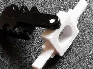
They fitted but were a little tight. I was happy with this as I didn’t want excess play in this pivot point, but then I didn’t want too much resistance either.
So after a little whittling of excess support material with a craft knife, I was happy with the clearances.
Similarly, I checked the chassis pivot clearances and with a few more seconds of trimming, I was able to turn the component freely in the chassis without there being too much play.
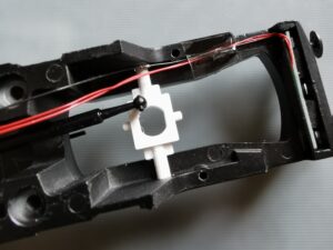
This picture shows the component inserted into the two holes in the chassis sides in its horizontal position. If anyone has ever disassembled these, they will know that this is the orientation required to remove/replace it from the chassis.
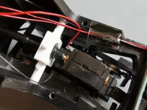
The component is then rotated 90 degrees so that the top/bottom pivot points are in the correct position, the bogie halves are split slightly to allow the bottom pivot point to be inserted. The driveshaft is inserted into the drive coupler (which goes through the central hole) being careful with alignment so as not to damage the drive splines.
Finally, the top clip was added… (located on the top pivot point), clips engaged and pressed down carefully but firmly.
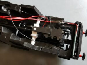
The final result.
Next check that the bogie is free to rotate and tilt freely without too much play. Repeat for the other end, and the job was done ready to test on the track.
Track testing was a success. As for longevity/durability, only time will tell. However, the PLA+ part is subjectively quite strong and should make a satisfactory substitute for the OEM part.
If you have a requirement for replacement components, then I would say have a go.