The V4.0 release of the EX_CommandStation (CS) firmware saw the incorporation of a ‘Hardware Abstraction Layer’ (or HAL) as part of the core code.
So what is this HAL? (Apart from a malevolent computer that wouldn’t open the pod bay doors!). Essentially this allows the easier integration of new hardware offering increased functionality to the original CommandStation to enable suitable hardware to operate points, signals accessories or read sensors amongst other things.
(For the technically minded out there, here is a link to the DCC-EX software developer’s description of the HAL DCC-EX HAL Architecture — DCC-EX Model Railroading documentation ).
Harnessing the Power of I2C – The Extra Hardware ‘Bits’
In its basic form, the ‘brains’ of the EX-CommandStation is the Arduino board. This interprets the WiThrottle commands (maybe from JMRI or an Android/iOS throttle App) and passes the complex DCC signals to the Motor Driver module (L298 Arduino shield) which connects and provides power and the complex DCC signals to your track and finally to the DCC Controller in your locomotive.

As mentioned above, the release of V4.0 EX-CommandStation’s firmware has allowed us to add more functionality to our layouts providing sensor and accessory support. For example, servo/s driving points/semaphore signal or LEDs for modern era signalling/general lighting around our layouts.
Until the introduction of V4.0 firmware, the ability of the Arduino to provide I2C Bus support has been there in the form of the I2C SDA/SCL pinouts but not used.
Version 4.0 (firmware) utilising the HAL unlocks that potential but some additional parts are required enabling the EX-CommandStation to be able to make practical use of I2C in the form of a 4 port I2C hub connected to the Arduino 5V rail and the Arduino SDA/SCL pins.
That sounds great but do I need to throw away my existing CommandStation and buy all over again?
Well no. As long as the software on your CommandStation is running Version 4.0 or later software, then we only need to add the extra hardware. The I2C hub…
The picture shows a 4 port I2C hub added to the basic CommandStation by simply removing the enclosure lid (4 screws), adding a joining part and the I2C hub part. Connect power and SDA/SCL wires to the Arduino carefully observing the correct orientation, then screw the lid back onto the newly installed hub.
This keeps the CommandStation modular meaning that existing users that wish to upgrade their original CommandStation may add the I2C hardware at a later date with minimal modification – only requiring the ability to use a screwdriver and inserting a 4-way plug the correct way round.
The I2C Bus – What is it?
Without getting too technical, the I2C Bus is a 2 wire connection (clock and data signals) between I2C compatible components. It can also be ‘daisy-chained’ onto further I2C devices as long as the overall wiring length is reasonably short. But more about that later. (Obviously, apart from the 2 wires, we also need a ground wire to join the bus components).
I2C was invented back in 1982 by Philips Semiconductor. A Wikipedia article can add far more information for the techies and/or curious – see I²C – Wikipedia
The 4 port I2C Hub add-on for the CommandStation (pictured above) offers 4 I2C ports (4-Way Grove style Connectors) to allow the connection of I2C compatible hardware via 4-way wiring. Note that each connector offers the two I2C signals (SDA and SCL) along with +5V and Ground (GND) (from the CommandStation Arduino).
I2C – What can I do with it?
With the advent of the Hardware Abstraction Layer (HAL) functionality in Version 4.0 CommandStation controllers, support became available for the connection of several I2C compatible controllers. Some examples:-
- GPIO Expanders (MCP23017, MPC23008, PCF8574)
- Servo/LED Controller (PCA9685)
These I2C compatible devices may be connected to the CommandStation’s I2C Hub using just 4 wires – SCL, SDA , +5V and GND.
Each device has an address which should be unique for each I2C device connected to the CommandStation.
So, for example. Two servo controllers (PCA9685) may be connected (each offering 16 outputs) but each controller must have different addresses (so that the Arduino can differentiate them).

Note also that there is not a standard for I2C bus wiring connectors or wiring sequence. So care must be taken when wiring the I2C controllers back to the I2C hub on the CommandStation. The I2C Hub add-on has 4 ‘Grove’ style sockets with the following pinouts (top to bottom):-
- G – Ground (GND)
- V – +5V
- SDA
- SCL
Each socket is polarised, thus a plug cannot be attached upside down. It is however easy to accidentally cross over the 4 wires when connecting to I2C peripherals. So be careful!
I2C – Where is this Bus headed? Next stop – Servo Controller (PCA9685)
So, we have the I2C CommandStation add-on and this needs to be connected to something.

It may be useful to connect some servos or LEDs to our CommandStation. Maybe we need to actuate some points or a semaphore type signal? Or maybe we have some colour light modern era type signals where we are using LEDS? Station/Platform lighting may also be a possibility and should be left to the imagination expertise of the modeller.
Well, this is where the PCA9685 component enters the picture.
The PCA9685 is an I2C compatible Servo driver module capable of independently controlling up to 16 devices. It may also be used to drive LEDs, so a combination of up to 16 Servos and/or LEDs may be connected to this one device.

Remember earlier we mentioned that each I2C device needs its own unique address? Well, that address may be set from the default value (0x0040) by bridging one set of solder pads (see below).
As supplied, the PCA9685 does not have any pads bridged thus the I2C address is 0x0040
Bridging solder pads A0 and A1 adds 3 to the address resulting in the I2C address of 0x0043
Servos/LEDs can take a fair amount of current (while moving) so a dedicated power supply (+5V) is connected to the green connector pictured top centre. I used a redundant mobile phone charger with around 2 Amps output while experimenting.
Care must be taken when connecting the +5V Power Supply. The +ve connection is the left hand screw terminal (as shown below). The right hand screw terminal is GND (ie the Power Supply -ve wire).
A 6-way Berg (DuPont) connector can be seen on the left side of the module. It has 6 connections of which we use 4 to connect to our I2C Bus.

- G GND
- SCL
- SDA
- VCC (to I2C Bus +5V supplied by Arduino Mega2560)
The other two pins, OE and V+ are unused. They are therefore removed (with side cutters) and the corresponding positions on the plug (which connects back to the I2C bus) are blanked off. This helps ensure the I2C plug is keyed and correctly connected to the module.
The correct orientation of this plug is important as it carries the +5v wire from the Controller’s Arduino module.
The 16 outputs from this versatile driver module can be seen at the bottom of the module. They are colour coded to help ensure attached servos/LEDs are correctly attached.
The picture shows an SG90 type servo which comes with a Berg style plug ready wired. The wiring is colour coded as shown and care must be taken when plugging the servo into the servo controller outputs.
As mentioned, LEDs may be driven by the servo controller. The LED cathode is connected to a GND output while its anode is connected to the PWM output via a series current limiting resistor. Many 3mm LEDs are able to operate down to 3mA forward current meaning that a series resistor with a value of 1 k Ohm may work giving good brightness. Less efficient LEDs will require a lower value series resistor to provide sufficient brightness.
I2C – Connecting It All Together
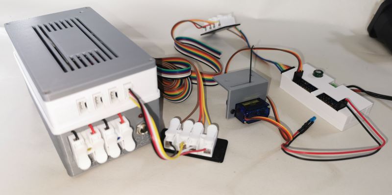
The picture shows a CommandStation with the I2C Add-on option fitted with four I2C sockets
I2C socket 4 (the right hand one) is connected via a short I2C bus cable and connected to a 4-way spring connector which may be attached to the underside of a layout’s baseboard with very sticky double sided foam mounting tape. (They may also be screwed to baseboards if preferred).
The other side of the spring connector strip is connected to a long ribbon cable (as I was testing I2C bus lengths) to another 4-way spring connector (top centre).
That is connected by a short ribbon cable to the Servo Module (PCA9685) in its 3D printed enclosure which may also be attached to the underside of baseboards. This module/enclosure is very light so maybe attached using very sticky double sided foam too.
The dedicated servo power supply is just off camera top right. I used a surplus mobile phone charger with the micro-USB plug chopped/stripped then attached to the PCA9685 – BE VERY CAREFUL WITH POLARITY unless expensive smoke is required!
One servo mounted onto a 3D printed bracket and linear wire is shown attached to the first servo module output.
An LED (blue and prototypically inaccurate for signalling!) is shown connected to position 16 of the servo module for testing purposes.
(Note that this picture shows an early prototype using coloured ribbon cable. Grey cable was used in later testing).
Testing a Servo Operated Semaphore and 2 Aspect Signal
To test the PCA9685 Servo Module, I 3D printed a semaphore signal and 2-aspect (Red/Green) modern day electric signal.
Two 1 metre 4 way ribbon cable lengths were also fabricated to check how the I2C clock and data signals might be affected by the sort of cable lengths required for a typical model railway layout. As touched upon above, the I2C bus was originally conceived for short distances, typically connecting devices on a circuit board. However in practice, longer runs of a few metres are achievable dependant of I2C clock speed, capacitance/resistance of connecting cables.
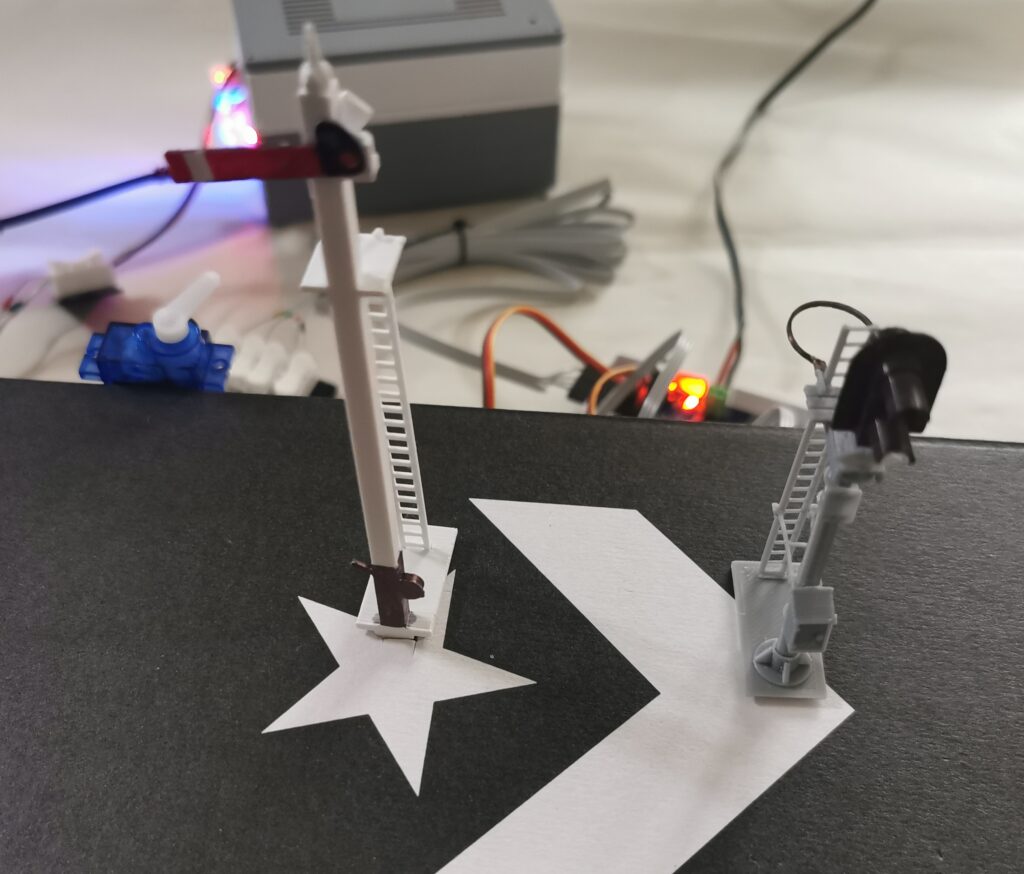
The 3D signals: assembled after 3D printing, given a touch of colour to make them look a little more interesting plus a standalone SG90 servo were attached to my test ‘jig’. A large shoe box! Unconventional maybe, but it gets the job done.
Credit for the 2 aspect electric signal used here must go to Thingiverse contributor ‘calvinstreeting’. The 3D Printer stl file for this can be downloaded from Thingiverse at https://www.thingiverse.com/thing:2300254
This signal uses 3mm Red/Green LEDS with the (small gauge) LED wiring running inside the signal pole.
Similarly, credit for the semaphore signal must go to ‘modelrailmusings’ who has made a range of GWR type semaphore signal designs at https://www.thingiverse.com/thing:3054199
To move the semaphore arm, fine spring wire runs inside the semaphore signal post and is actuated by a SG90 servo which is attached to a 3D printed SG90 servo mount designed for this project.
The semaphore servo and LEDs are wired back to the PCA9685 Servo Module housed in its 3D printed enclosure (see below).
This schematic adds more detail to the test setup:-

One short (20cm) I2C cable was supplied with each 4 port hub used to make the CommandStation add-on hub. This was cut providing two even shorter cables for expanding the bus on to I2C compatible peripherals.
4-way spring clip connector blocks were made to allow a longer (100cm) 4-way ribbon cable to be connected thus extending the bus to approximately 110cm. Note that the long ribbon cable lengths had their end stripped and tinned to allow them to be connected to the spring connectors. Each wire was sleeved with heat shrink tubing to allow easier identification of the 4 wires.
- GND – Black
- VCC – Red (+5V which powers the PCA9685 module from the CommandStation)
- SDA – White (but shown as grey on the above diagram)
- SCL – Yellow
(The colour coding was chosen to match the cables supplied with the I2C hub component).
A further 100cm 4-way ribbon cable had a 6 way DuPont connector attached allowing connection from the second 4-way spring connector to the PCA9685 servo module. (Unused pins on the PCA9685 were removed and the corresponding positions on the DuPont plug were plugged thus keying it and making it less likely to be inserted into the PCA9685 module wrongly.
So with the two 1m ribbon cable runs plus the I2C grove cable, the total bus cable length from the CommandStation to the PCA9685 module is in the order of a little over 2.1 metres. So will it work?
Modifying the CommandStation Software to Enable the I2C Bus
Now that the hardware has been assembled and wired to the CommandStation, the next task is adding additional information to the CommandStation software that will define the pins (from the PCA9685) to be used to turn the 2 Way Aspect LEDs on and off and move the semaphore signal.
This involves modifying the Arduino Sketch within the Arduino IDE. Compiling that sketch and uploading it to the CommandStation.
In testing, the latest (at the time Version 4.2.5 development) software downloadable from the official DCC-EX repository was used.
(Be aware of the caveat that 4.2.5 is development software so may include bugs/’funnies’ and may do unpredictable things). You have been warned!
In practice I haven’t discovered anything to make my pulse race and I like to live dangerously!
Defining Servos
WARNING – THE EXAMPLE SERVO CONFIGURATIONS BELOW ARE PROVIDED FOR DEMONSTRATION PURPOSES ONLY AND RELATE TO THE TEST ‘JIG’ DESCRIBED ABOVE.
Please read the official DCC-Ex documentation when defining YOUR servo controls as the servo rotation parameters will be unique to your setup. Copying the below servo configurations may damage your servos and/or equipment connected to them if inappropriate values are used.
In this test setup, two servos are connected to the PCA9685. One driving the semaphore signal and the other standalone used to observe how the servo setup parameters in software affect the positioning of the servo horn.
Referring to the above schematic, the standalone servo is connected to the left most three pins of the 16 columns of 3 pins (coloured yellow, red and black). The pins groups are numbered 0 to 15 (left to right) therefore the standalone servo is connected to pin group ‘0’ of the first PCA9685 connected to the I2C bus (in fact the only one as this test stands).
Pin groups 0 to 15 on the first servo controller are referred to by the CommandStation software as vpins 100 to 115
Therefore the standalone servo is at vpin 100 when defining it in software (see later).
Similarly, the semaphore signal servo is connected to the next group of three pins (group 1), The CommandStation reference for this servo is 101 (its vpin). Just add 100 to the pin group number for the first servo controller on the I2C bus to obtain the CommandStation vpin number for the first servo controller.
Add Servos to myAutomation.h
Servos used for mechanically operated signals (eg. Semaphore) require servo position and an actuation profile when defining each servo. Three numbers representing the signal positions: red_position, amber_position and green_position are defined. The profile setting sets the speed of actuator movement ranging from Slow, Medium, Fast to Instant. There is also a special speed setting ‘Bounce’ which simulates the bounce of a semaphore signal being changed.
The servo type used here (SG90) has an output shaft that can rotate through 0-180o
An actuator horn (little plastic arm with small holes drilled along its length) is attached to the output shaft.
The position of the horn (angle) and the operation speed can be defined using the SERVO_SIGNAL directive in myAutomation.h
Open the Arduino sketch myAutomation.h tab and add the two lines (highlighted below) to define the standalone servo (SERVO_TURNOUT named Servo_Test) and the semaphore servo (SERVO_SIGNAL).
The SERVO_TURNOUT and SERVO_SIGNAL parameters are explained further down and are referenced in the official DCC-EX documentation at https://dcc-ex.com/ex-commandstation/accessories/signals/servo-signals.html
The servo position parameters used here are appropriate for the test setup described above and WILL require ‘tuning’ for your particular usage. Incorrect parameter values may damage servos and/or the equipment connected to them! You have been warned! It is advised that servo angle parameters are tested and observed before attaching a linkage to any signal/device.
SERVO_TURNOUT(200, 100, 450, 110, Slow, "Servo_Test")
SERVO_SIGNAL(101, 280, 0, 250)
Defining Outputs (to Drive LEDs)
The Red and Green 2 Aspect Signal LEDs are defined in mySetup.h
Each LED is connected to a different PCA9685 pin group. Red to 14 and Green to 15. (The LEDs have a common ground that may be connected to the Ground pin of either pin group. (In the above schematic it is connected to pin group 115).
Add Outputs (LEDs) to mySetup.h
Open the Arduino sketch mySetup.h tab and add the following highlighted block to define the two LEDs connected to vpins 114 (Red) and 115 (Green).
Notice that for each LED, there is an IODevice and a SETUP line.
// Setup two LEDS
// An LED with anode (positive) to PWM pin set for full intensity when turned on
// vpin = The VPin the LED is connected to, eg. 101 for the second pin on the first PCA9685 //servo module (range 100-115)

IODevice::configureServo(115,4095,0,PCA9685::NoPowerOff);	//vpin 115 (last pins of first servo module)
                                                                //intensity,full (intensity)=4095,off(intensity)=0
IODevice::configureServo(114,4095,0,PCA9685::NoPowerOff);	//ditto vpin 114 (but using 2nd to last PCA9685 pins)

SETUP("<Z 500 115 0>");          //Define an "output" with ID 500 to match the LED (Green) connected to VPin 115 (see above)
SETUP("<Z 501 114 0>");          //Define an "output" with ID 501 to match the LED (Red) connected to VPin 114 (see above)
Compile and Upload the Modified Sketch to the CommandStation
The modified sketch is compiled and uploaded to the CommandStation
15th May 2023 WIP. To be added – configure, test devices