Build your own EX-CommandStation – A DIY entry-level DCC Controller based on the DCC-EX Project.
3D Printable files are available for the Mk1 version of the Commandstation and may be downloaded from the Thingiverse Website at ‘Railsnail’ DCC-EX (Mk1) Enclosure by Railsnail – Thingiverse
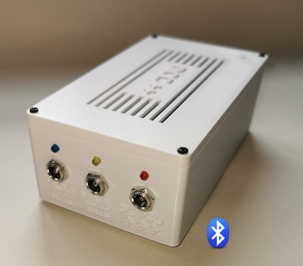
This version is Bluetooth connected meaning that your railway layout may be controlled wirelessly from a suitable DCC App on a phone/tablet OR Bluetooth enabled PC/Laptop/Mac.
IMPORTANT – Apple devices running the Apple IOS operating system (ie iPhone and iPad) ARE NOT compatible with this Commandstation
In keeping with the DCC-EX current design philosophy, the microcontroller board used in this design is the Arduino Mega2560 (or clone).
DCC signals to the MAIN or PROG tracks are derived from an Arduino Motor Shield that simply piggy-backs off the Mega2560 microcontroller.
The whole CommandStation is powered by one DC power supply (+15V DC) fitted with a 5.5mm x 2.1mm DC plug. A buck converter module (LM2596) reduces the input voltage to 7.5V DC to power the Arduino Mega2560 and Bluetooth module (HC-05).
Output to the MAIN and PROG tracks is via 5.5mm x 2.5mm DC sockets. The use of 2.5mm centre pins should ensure that the DC Power Supply cannot be connected to these sockets accidentally, causing damage to the CommandStation.
DCC commands input to the CommandStation is via a Bluetooth HC-05 Module which is powered by 5V DC (from the Mega2560). The HC-05 serial data input/outputs are not 5V compatible thus requiring level conversion to safely drive the data input to the HC-05. This is achieved by modifying an ESP01 3.3V 5V ESP-01 Serial Adapter thus safely converting 5V logic levels from the microcontroller to 3.3V levels suitable for the HC-05.
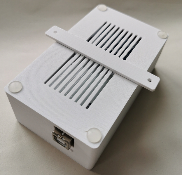
Finally, the CommandStation is housed in a suitable enclosure. In this example, a 3D printed PLA enclosure was designed and printed specifically for this project, although any enclosure (116mm long x 68mm wide x 40mm high) or larger should suffice.
3D Printable files are available for the Mk1 version of the Commandstation and may be downloaded from the Thingiverse Website at ‘Railsnail’ DCC-EX (Mk1) Enclosure by Railsnail – Thingiverse
Parts List
- 1x Arduino Mega 2560
- 1x Arduino Motor Shield
- 1x HC-05 Bluetooth Module (for type/variant, see text)
- 1x LM2596 Buck Converter Module
- 1x ESP8266 ESP-01 Serial Adapter (modified, used for 5V/3.3V level conversion) OR
- 1x Prototype Board Cut to size + 2.54mm Female Connector + 2kOhm + 1kOhm resistors (to make level converter board)
- 1x 15V DC 3A Power Supply (3A recommended) – With 5.5mm 2.1mm plug (centre pin positive). *
- 1x 3mm Pre-wired Red LED (incorporating 1.2kOhm series resistor)
- 1x 3mm Pre-wired Yellow LED (incorporating 1.2kOhm series resistor)
- 1x 3mm Pre-wired Blue LED (incorporating 1.2kOhm series resistor)
- 2x 470 Ohm 1/4W resistors (470 Ohm suggested, but actual value dependant on LED forward Voltage/Current rating)
- 5x Mini Micro JST-PH 2.0 JST – 2 Pin Male Plug Connector Cable. Pre-wired/Crimped
- 5x Mini Micro JST-PH 2.0 JST – 2 Pin Female Plug Connector Cable. Pre-wired/Crimped
- 1x 5.5mm 2.1mm Female DC Power Socket (Power In)
- 1x 5.5mm 2.1mm Male DC Power Plug (Power In)
- 2x 5.5mm 2.5mm Female DC Power Socket (Main/Prog)
- 2x 5.5mm 2.5mm Male DC Power Plug (Main/Prog)
- 2x 2 way 2.54mm single right-angle PCB connector
- 30AWG multi-strand wire – Red, Blue, Yellow and Green
- Heat-Shrink tubing – various to suit
- Enclosure – 3D Printed (Or a proprietary plastic enclosure of suitable size (116mm long x 68mm wide x 40mm high)
- 4x Self-tapping Panhead screws – M2.3 x 8 To secure enclosure’s lid
- 4x Stick on feet – For enclosure
- Double-sided sticky pads
* DC Power supplies with plug size different to 5.5mm 2.1mm will require plug removal and replacement ensuring the centre pin of the replacement is wired to DC positive!
Interconnecting Cables/LED Connections
Where possible, readily sourced pre-made (JST-PH 2.0) cables and 3mm LED assemblies have been used as this reduces soldering/crimping of connectors increasing reliability and reducing soldering to a minimum. At the time of writing, cables and pre-wired LEDs are available from Amazon UK.
Using these cable types allows the CommandStation’s external sockets (Power, Main and Prog Track) to be conveniently connected/disconnected to/from the internal modules (Mega2560, Arduino Motor Shield and LM2596 Buck converter) allowing for easier servicing and build.
Careful selection of male/female JST-PH JST connector combinations should avoid incorrect interconnections between the modules and DC sockets.
Pre-wired 3mm LED assemblies have also been used that incorporate 1.2k ohm series resistors as supplied. (The resistors are not shown on the assembly diagram below).
Two additional series resistors, (R1 and R2), connected in series with the LEDs that indicate Main and Prog Track power are included due to the higher voltages output on these sockets. These resistors are soldered directly onto the DC (Main and Prog Track) socket terminals and covered in heat-shrink tubing. (See the construction directions below). Suggested values of 470 ohms may change according to the max forward current value of LEDs used.
Note that the wire lengths shown below are given as a guide in the construction notes assume that the 3D printed case dimensions (116mm long x 68mm wide x 40mm high) and module locations have been followed.
Larger enclosures/Differing layouts will require different wire lengths to those shown below.
Construction
Solder Mega2560 Power Supply Wire
The 3D printable enclosure design downloadable from the Thingiverse Website at ‘Railsnail’ DCC-EX (Mk1) Enclosure by Railsnail – Thingiverse can house a genuine Arduino Mega2560 module OR a Mega2560 clone. (Locations of the USB and Power Supply Socket differ slightly between the two versions). The 3D case design can accommodate both variants with optional printable port covers hiding any gaps caused by the differences.

(Pre-wired JST-PH 2.0 Male/Female Power connectors are used in this build therefore crimps are not required, and red/black wires can be cut to the required length).
CBL1 – Take a female JST-PH 2.0 part. Cut wires to a length of 120mm approx. and strip, tin and solder the red and black wires to the +ve/-ve pads/vias on the underside of the Mega DC socket.
(The picture shows the Mega2560 Power Supply Socket removed. Just solder the red and black wires to the corresponding pads on the underside of the board).
LM2596 Buck Converter Module Wiring
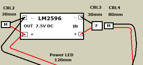
CBL-2 – Cut the wires to a male JST-PH 2.0 part to 30mm length. Strip, tin and solder the red and black wires to the Buck converter’s output terminals. Observe DC polarity. (See diagram).
LED1 ‘Red Power LED’ – Cut the wires on the RED 3mm LED/Resistor assembly to 120mm length. Strip, tin and solder the red and black wires to the Buck converter’s output terminals. Observe DC polarity.
Mega2560/HC-05 Bluetooth Data Level Adapter
Although the Bluetooth module (HC-05) may be powered from a 5v DC supply, the data connections are not 5V tolerant.
This is not an issue for the TX data output FROM the HC-05 to the Mega2560 however the RX data input INTO the HC-05 may be damaged when connected to the Mega2560 TX and will require some additional circuitry to deal with this.
Two options are described. The first, (and preferred option), is to modify a ‘level converter’ adapter designed for ESP8266 (ESP-01) modules, the second is to make a level converter ‘add-on’ using a cut-down piece of prototype board, a 6 way 2.54″ female socket and two resistors.
The two options are detailed below:-
Option 1 – Connect the HC-05 Bluetooth and ESP-01 Adapter Modules
Remove the 8-Way ESP-01 connector from the ESP-01 Adapter Module. The connector may be gently prised from its pins using small pliers. The 8 pins remaining are then easily de-soldered.
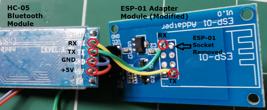
Cut a 20mm approx. length of yellow 30AWG wire. Connect HC-05 RX pin to the ESP-01 Adapter TX pin (see below picture).
Cut a 20mm approx. length of green 30AWG wire. Connect HC-05 TX pin to the ESP-01 Adapter RX pin (see picture).
Cut a 20mm approx. length of red 30AWG wire. Solder one end of it to the solder pad marked +5V on the HC-05 module.
Solder the other end to the solder pad marked VCC on the ESP-01 Adapter module.
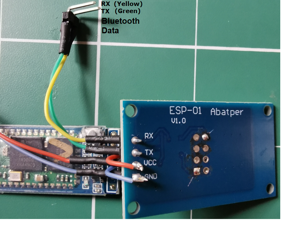
Cut a 20mm approx. length of blue 30AWG wire to approx. 20mm length. Solder one end of it to the solder pad marked GND on the HC-05 module. (see above photo)
Solder the other end to the solder pad marked GND on the ESP-01 module. (see photo – right)
Attach the HC-05 module to the top surface of the ESP-01 Adapter module using a double-sided sticky pad.
Option 1 – Attach Power and Data ‘flying’ leads to the ESP-01 adapter connector:-
RX/TX Data – Cut approximately 30mm of green and yellow 30AWG wire. Solder the green wire to the ESP-01 Adapter Module TX connector and the yellow wire to RX. Insulate connections with heat-shrink tubing. (see above photo)
Solder the other ends of these wires to a two-way 2.54mm single right-angle PCB connector observing orientation. Insulate with heat-shrink tubing.
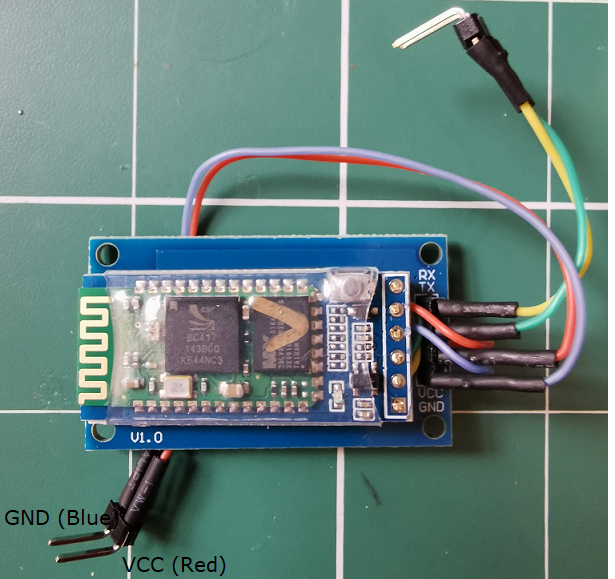
Power – Cut approximately 60mm of red and blue 30AWG wire.
Solder the red wire to the ESP-01 VCC adapter connector.
Solder the blue wire to GND.
Insulate connections with heat-shrink tubing. (see photo – right)
Solder the other ends of these wires to a two-way 2.54mm single right-angle PCB connector observing orientation.
Insulate with heat-shrink tubing.
Option 2 – Prototype Board Level Converter
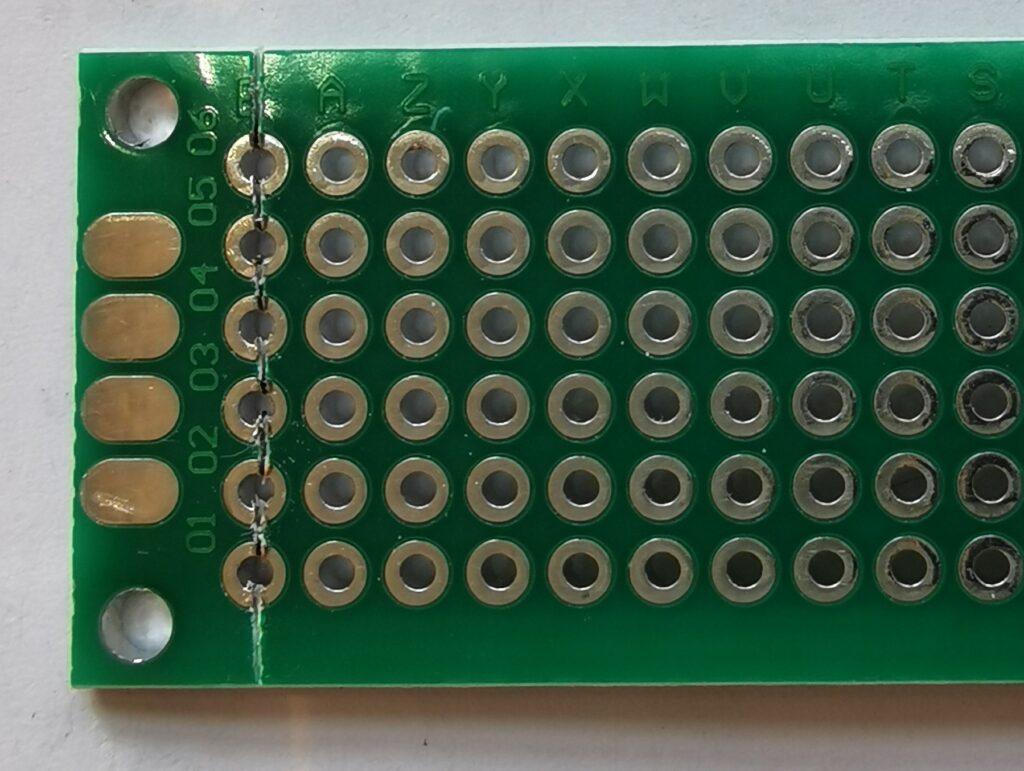
6-way prototype board is ideal for making the level converter. It is easy to cut by scoring the board with a sharp craft knife (on both sides), then breaking it off with pliers.
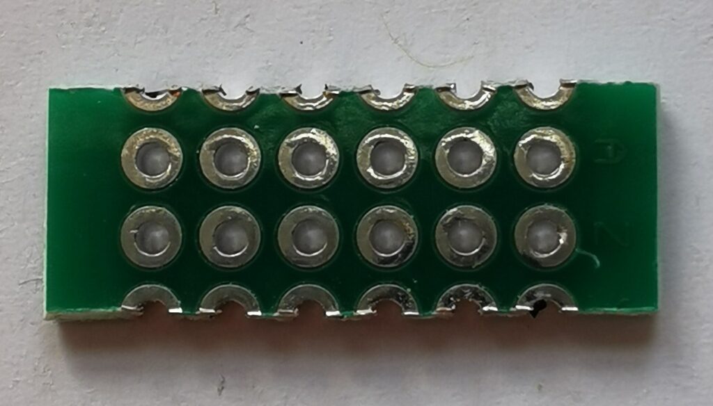
Do this, to make a small board with 2 rows of 6 complete solder pads.
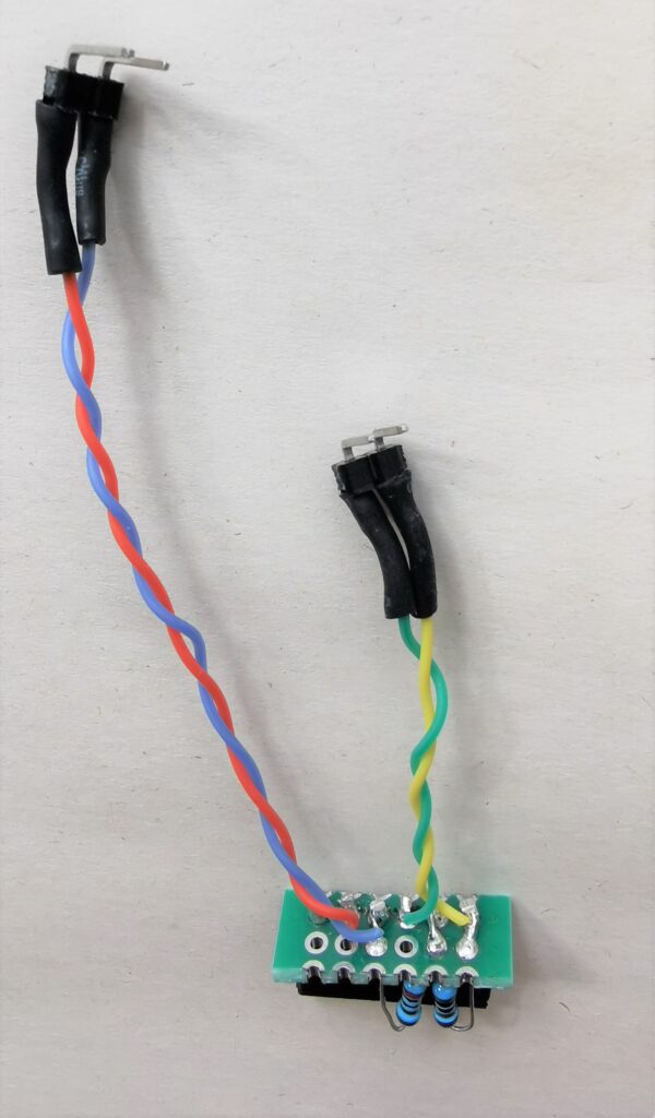
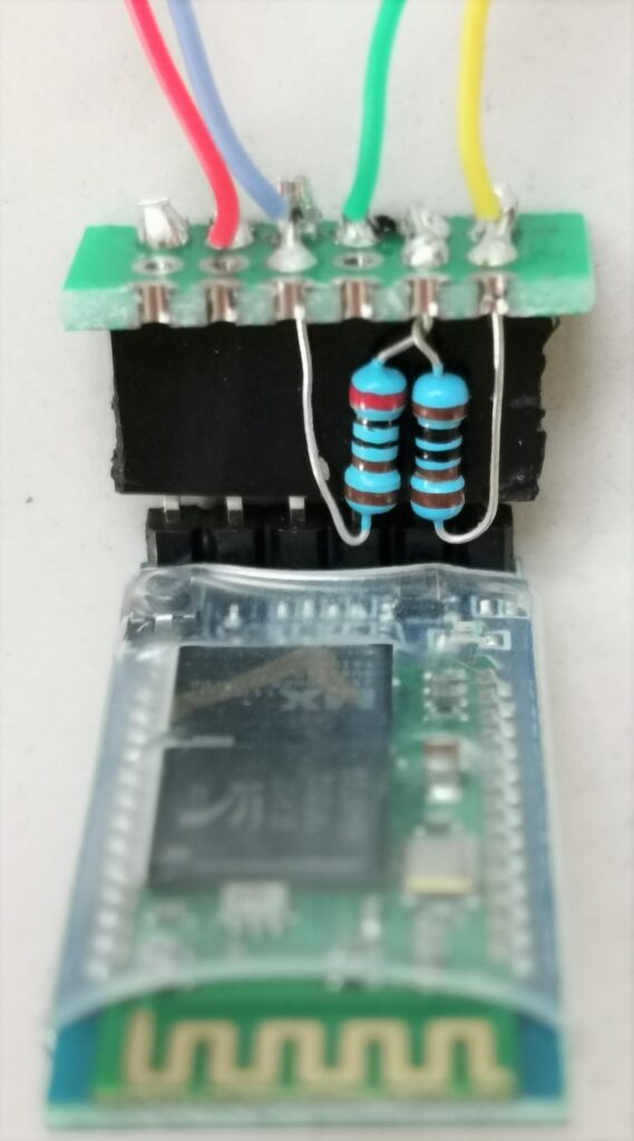
Solder a 6-way Female connector to one of the rows, and two resistors (1kOhm and 2kOhm) as shown to form a potential divider to convert the Mega2560 TX data output to levels that the HC-05 can tolerate. (See photos and diagram).
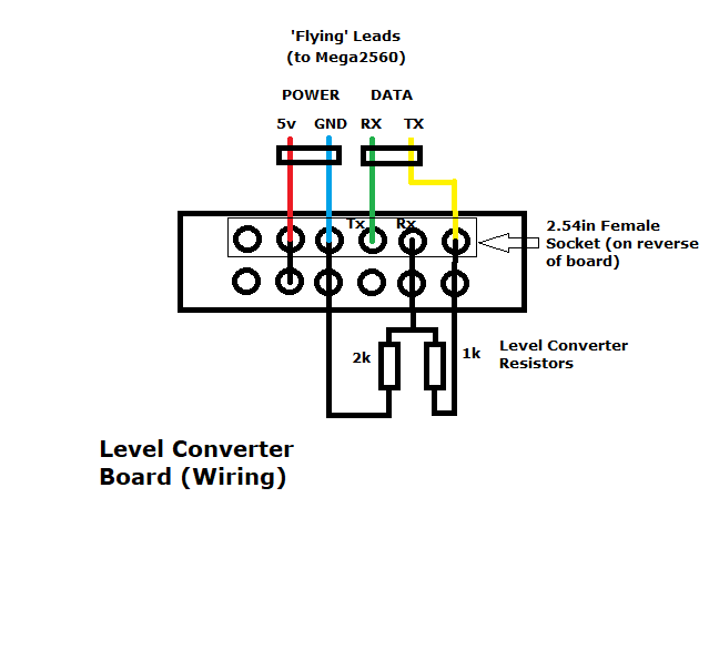
Option 2 – Attach Power and Data ‘flying’ leads to the Level Converter Board:-
RX/TX Data – Cut approximately 30mm of green and yellow 30AWG wire. Solder them to the Level Converter Board (see above photo).
Solder the other ends of these wires to a two-way 2.54mm single right-angle PCB connector observing orientation. Insulate with heat-shrink tubing.
Power – Cut approximately 60mm of red and blue 30AWG wire.
Solder these to the Level Converter Board (see above photo).
Solder the other ends of these wires to a two-way 2.54mm single right-angle PCB connector observing orientation.
Insulate with heat-shrink tubing.
Option 2 – Attach Level Converter Board to HC-05 Bluetooth Module
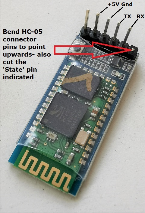
Before attaching the completed Level Converter to the HC-05, bend the 6 connector pins of the HC-05 so that they are at 90degrees to the module (ie pointing upwards). Cut the pin labelled ‘State’
(See photo)
Connect the Level Converter to the HC-05 pins. (Check carefully for correct alignment. ie the Red +5v and Blue GND connections must align with +5v/GND as marked on the HC-05 module).
Bluetooth ‘Reset’ Add-on (for use with Option 1 above)
(Programming the Arduino via Bluetooth)
The HC-05 Bluetooth (BT) module interfaces directly with the TXD0/RXD0 data pins of the Arduino.
These are the same pins used by the USB converter circuitry, thus the BT data signals are effectively in parallel with the USB data signals. This means that in theory the Arduino may be operated AND programmed from the BT connection without having to use USB.
In practice, one extra ‘trick’ is required to allow the programming function so that the Arduino ‘knows’ new software is being uploaded and its bootloader must be run.
Normally, when programming/uploading new software (eg in the Arduino IDE), a signal is sent (via USB) to the Arduino which resets the Mega2560 chip thus running the Bootloader software programmed onto the Mega.
In order to create this Reset signal from the BT connection, we need to set up the HC-05 (in AT mode) to set its STATE output pin to a logic low level when the BT connection is active (set the HC-05 Status Pin ‘active low’ with the AT command AT+POLAR=1,0).
By de-coupling this signal through a capacitor, it will momentarily reset the Arduino. (The RESET line on an Arduino Mega2560 is active low).
This will run the Bootloader software (when BT connects) which then takes the serial data which follows and programmes the Arduino.
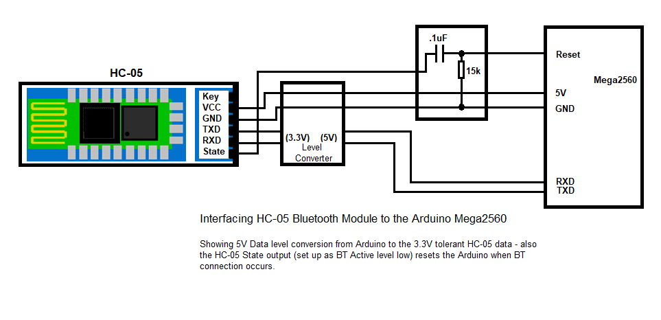
The extra add-on circuitry can be seen in the above diagram. The HC-05 STATE pin is connected to a 0.1uF (100nF) capacitor which is connected to the RESET connector on the Arduino. (The addition of a 15k ohm resistor connected to ground pulls the RESET voltage down to a level detected high by the Arduino, but at a voltage where the low going pulse from the capacitor (created when BT connects) will reset the Arduino thus running the bootloader.
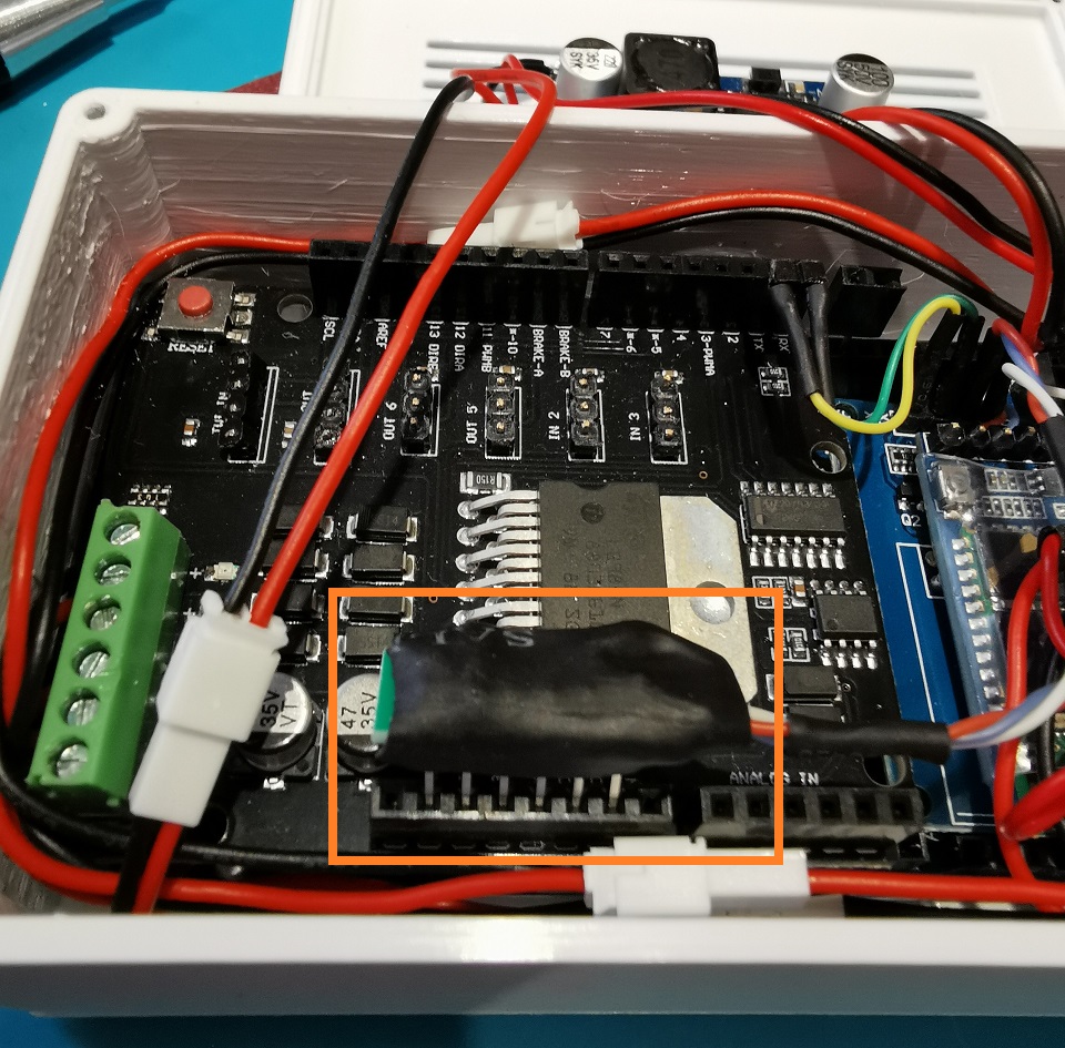
The add-on circuitry may be built onto a small piece of prototype board with a 6 pin header attached. Flying leads connect to the BT 5V to 3.3V level converter and STATE pin (from the HC-05). This assembled add-on may be enclosed in heat shrink tubing then attached to the Arduino RESET, +5V and GND connector. (see below).
POWER, MAIN Track, PROG Track, Sockets and LED Indicators
Cut the following to length before soldering to the DC connectors:-
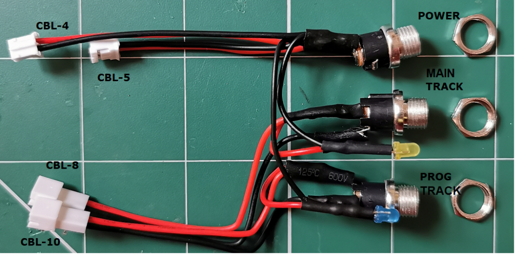
- CBL-4 – (To LM2596 Power In) Cut the wires on a male JST-PH 2.0 part to approx. 80mm length.
- CBL-5 – (To Motor Shield Power In) Cut the wire on a female JST-PH 2.0 part to approx. 100mm length.
- CBL-6 – (To Power Connector) Cut the wires on a male JST-PH 2.0 part to approx. 60mm length.
- CBL-7 – (To Motor shield B terminals) Cut the wires on a male JST-PH 2.0 part to approx. 65mm length.
- CBL-8 – (To MAIN Track DC Socket) Cut the wires on a female JST-PH 2.0 part to approx. 95mm length.
- CBL-9 – (To Motor shield A terminals) Cut the wires on a male JST-PH 2.0 part to approx. 65mm length.
- CBL-10 – (To PROG Track DC Socket) Cut the wires on a female JST-PH 2.0 part to approx. 95mm length.
- LED2 – (Yellow MAIN Track Power On Indicator) – Cut the wires to a length of approx. 50mm
- LED3 – (Blue PROG Track Power On Indicator) – Cut the wires to a length of approx. 65mm
With reference to the following diagram and above picture, solder the cables/LEDs to the 3 DC Connectors carefully checking polarity and DC Connector pin sizes. DC Power Socket Centre pins (tip) is positive.
The (DC) POWER socket has a 2.1mm dia centre pin size while the MAIN Track and PROG Track Sockets centre pin size is 2.5mm dia. Do not mix these.

CommandStation Assembly
Check thoroughly for the polarity of all connections. A little time spent here may save smoke and problems later!
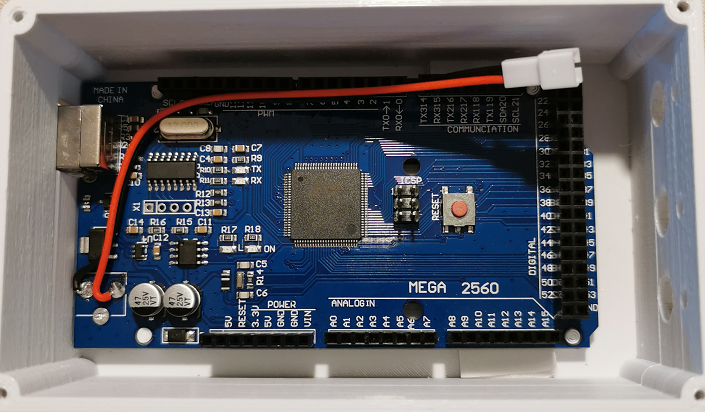
Attach double-sided sticky pads to the underside of the Arduino Mega2560, then locate it into the 3D printed enclosure, ensuring the PCB locating holes line up with the enclosures stand-offs and the module is firmly attached to the enclosure.
When deciding on the location of the sticky pads, make sure that there is sufficient airflow into the enclosure through the bottom grilles and around the PCB.
The sticky pads should retain the Mega2560 securely in position but will allow the board to be removed should the need arise.
Arduino Motor Shield

Cut the unused Header Pins, (20 in total marked in red on the picture), located on the top side of the Arduino Motor Shield using strong side cutters.
Cutting these will reduce the possibility of the LM2596 Buck Converter components (mounted above the motor shield) coming into contact with these pins.
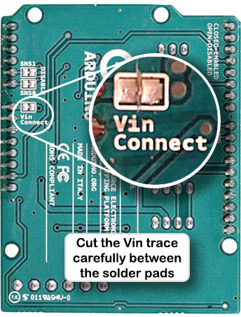

WARNING!
As stated in the EX-CommandStation Official Build Documentation.
The Vin trace must be cut on the bottom side of the Arduino Motor Shield.
Failure to do this will result in catastrophic damage to the Mega2560/Bluetooth Module/Buck Converter.
Make the cut using a craft knife or similar. Then check that the two pads shown ARE ISOLATED with an ohm-meter
Take the cables CBL-5, CBL-7 and CBL-9 and insert the stripped ends into the (Green) Arduino Motor Shield screw connector and tighten the screws. (see above Connection Diagram for connection orientation details).
Check again that the Vin trace has been cut on the reverse of the Arduino Motor Shield. (See above warning).

Attach the Arduino Motor Shield to the Arduino Mega2560 ensuring all the inter-connecting pins are correctly aligned and not bent (see picture). Press the module firmly onto the Mega2560 connectors.
Attach double-sided sticky pads to the underside of the ESP-01 Adapter/HC-05 Bluetooth module pair and stick these modules onto the top of the Mega2560 PCB at the position shown ensuring the Mega RESET switch is not pressed down by modules.

Connect the two flying leads:-
- The Power flying lead connects to Arduino sockets marked +5V (red) and GND (blue)
- The Data flying lead connects to Arduino sockets marked TX0 (yellow) and RX0 (green) as shown.
Double-check the power leads are aligned correctly else damage will occur!
Attach a double-sided sticky pad to the underside of the LM2596 Buck converter, locate it onto the underside of the 3D printed enclosure lid ensuring the PCB location holes fit onto the moulded stand-offs. The lid should be orientated with the ‘Reset’ hole as shown.
Make sure it is securely attached to the enclosure lid and the orientation is as shown below (i.e. Input terminal on the right, output left). A dab of glue on each stand-off should ensure the converter is securely attached and will not drop off the lid.
IMPORTANT. Rotate the trimmer potentiometer located on the Buck converter fully anti-clockwise. (This will set the converter output voltage to a minimum thus avoiding possible over-voltage damage later).
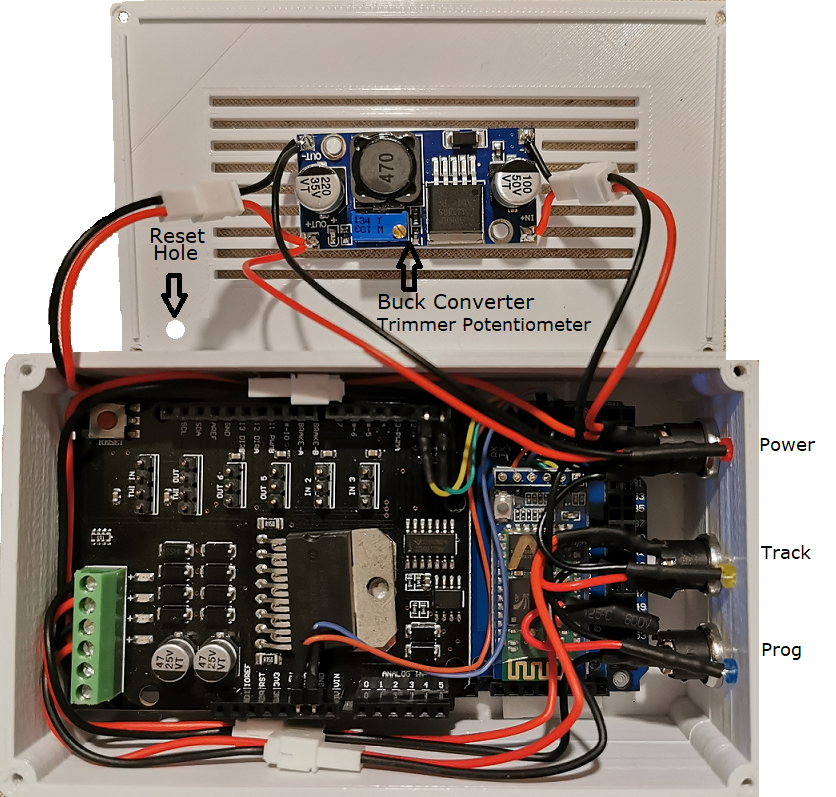
Insert the DC sockets and LEDs into their enclosure locations as shown.
In the above photo, the POWER socket (with 2.1mm centre pin) is located top right as shown (adjacent to red LED).
The centre socket is the MAIN track output (with a 2.5mm centre pin). The LED indicator is yellow.
The last socket is PROG track output (also with a 2.5mm centre pin) with a blue LED indicator.
Secure the sockets with the supplied nuts and apply a small blob of glue around each LED on the inside of the enclosure to prevent the LEDs from working loose.
Set The Buck Converter Output Voltage
Disconnect all JST-PH 2.0 connectors (if connected).
WARNING. Rotate the trimmer potentiometer (the blue component in pictures above) located on the Buck converter full anti-clockwise. (This will set the converter output voltage to a minimum value thus avoiding possible over-voltage damage later).
Connect the 15V DC Power Supply to the DC POWER socket and connect it to mains power.
Slowly rotate the Buck converter trimmer potentiometer in a clockwise direction while monitoring the output of the converter with a voltmeter until the voltmeter reads 7.5V +/- 0.2V
The POWER LED should illuminate red.
Disconnect the 15V power supply and connect all the JST-PH 2.0 plugs and sockets as shown in the above connection diagram/photos.
Inspect soldered connections to ensure correct polarity. Also, ensure that the JST-PH 2.0 connectors have not been supplied with any incorrectly terminated sockets.
It is worth taking some time checking everything at this point, as it may result in less smoke and damage later!
This completes the assembly, but do not attach a lid to the enclosure until the HC-05 Bluetooth Module has been set up.
HC-05 Bluetooth Module Information and Setup
The Bluetooth module used in this EX-CommandStation (Bluetooth) controller is the HC-05 which is capable of communicating with a Bluetooth host with a range of approximately 10 metres.
This document does not go into any great depth regarding these devices. Much greater insight into these may be found at Martyn Currey’s excellent site http://www.martyncurrey.com/hc-05-with-firmware-2-0-20100601/
They are easily obtainable, but there are several variants of this device. This document currently covers one type of HC-05 only. (Other types may be incorporated later). The HC-06 Bluetooth module type is another candidate for use in this project, however, the number of variants of these resulted in the decision to stick with just the HC-05 module.
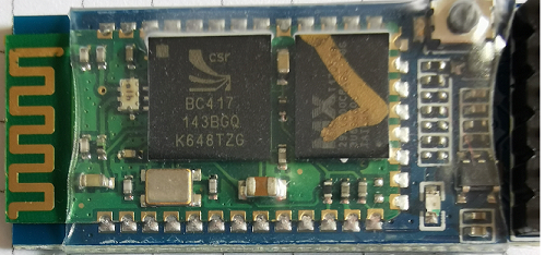
The Bluetooth module type used in this project is often known as the ‘Old’ variant of the HC-05. Here are close-up pictures of two modules that are supported here, showing the front and back of each module.
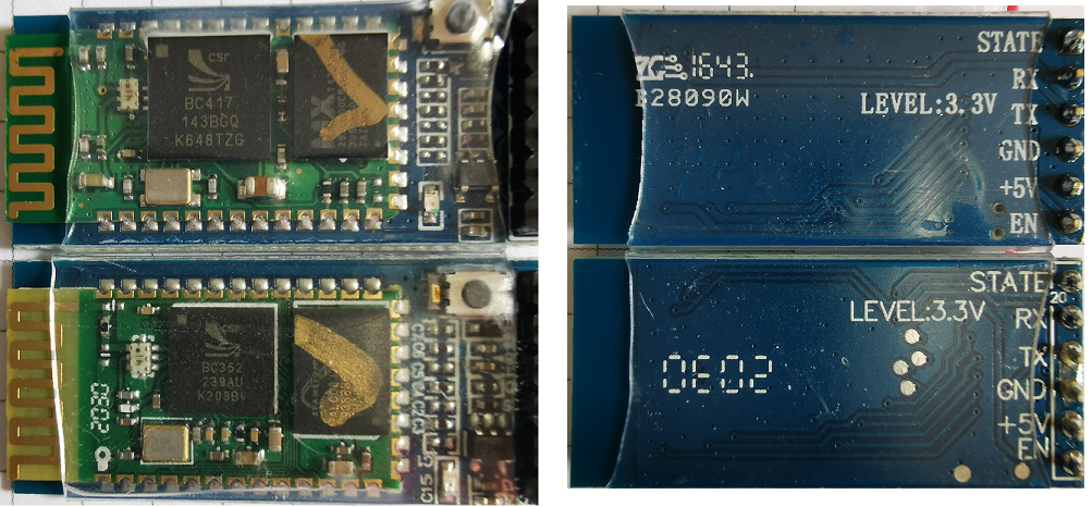
The top module, marked B28090W, is an older device sourced from an eBay seller around 2017. The firmware version when checked with the command ‘AT +VERSION’ returned VERSION:2.0-20161226
The lower device, marked 2030 (manufactured week 30 of 2020 maybe?), was sourced very recently from an eBay seller and was described as an older variant of HC-05. (Both modules use two large chips on the Bluetooth carrier board). The firmware version number of this module when checked with the command ‘AT +VERSION’ returned VERSION:3.0-20170601
Notice the button switch located on the top of the module adjacent to the connector. This will be used later to enable us to put the module into ‘AT’ Programming mode as the HC-05 must be programmed to communicate on its serial port at 115200 BAUD. Also, by default, it broadcasts a Bluetooth name HC-05 and has a pairing PIN 1234.
All of these parameters may be changed by temporarily connecting the HC-05 Serial Data pins to UART3 on the Mega2560, then downloading and compiling a sketch to enable these HC-05 settings to be changed. (See details below).
Other variants of HC-05 may have different chips/carrier boards. These may work, but require a different procedure to program them. (More information on other variants may be found at Martyn Currey’s Website).
Finally, there is another type of Bluetooth Module readily available known as JDY-31. These cannot be used for this project.
‘AT’ Programming – Set the Bluetooth Baud-rate and Name/PIN settings
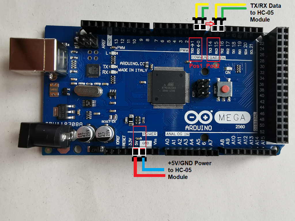
Power – disconnect the Bluetooth Data flying leads (green/yellow) from the Mega2560 TX0/RX0 female sockets marked RX0(0) and TX0(1). (Pos1 in the picture).
Reconnect these to Mega UART 3 female sockets marked TX3(14) and RX3(15). The yellow wire goes to RX3 and green to TX3. (Pos2 in the picture).
It is assumed that a working installation of Arduino IDE is available. If this is not the case, then refer to the official EX-CommandStation software installation documentation explaining how to install the Arduino IDE and download the latest software. This may be found at https://dcc-ex.com/get-started/arduino-ide.html
Install the Bluetooth Setup Sketch.
In the Arduino IDE, create a new sketch
Copy the following code into the new empty sketch OR Download the sketch from the GitHub and insert it into the new sketch.
// Bluetooth setup sketch (Arduino Mega version). Version 1.2 - 27th Dec 2021
//
// Serial UART 3 (at 38400 BAUD) is used for communication with the Bluetooth module.
// USB Serial (at 9600 BAUD) connects to the computer

void setup()
{
    // Mega USB port communication set to 9600 BAUD
    Serial.begin(9600);
    delay(500);

    Serial.println("Arduino Mega 2560/HC-05 Simple Bluetooth Terminal/DCC++ Setup - 271221");
    Serial.println("----------------------------------------------------------------------");
    Serial.println(" ");
    Serial.println("IMPORTANT Pre-checks ");
    Serial.println("1. Arduino Serial Monitor Setup:- Both NL & CR is selected AND BAUD rate is set to 9600.");
    Serial.println("2. The HC-05's serial data flying leads (green/yellow) are connected to Mega UART 3 (pins 14/TX3/yellow and 15/RX3/green)...");
    Serial.println("3. The HC-05's power flying leads (red/blue) are connected to Mega +5V/Gnd ...");
    Serial.println("4. Ensure the HC-05 is in 'AT' mode when the Arduino/HC-05 is powered on by...");
    Serial.println(" ");
    Serial.println("Powering on the Controller/HC-05 with the small button on the HC-05 pressed");
    Serial.println("Then release the button - The LED on the HC-05 should now flash on/off every 2 seconds (approx.)");
    Serial.println("-------------------------------------------------------------------------------------------------");

    Serial.println(" ");
    Serial.println("First we will check that the Mega can communicate with the HC-05 by sending the AT+VERSION command.");
    Serial.println("If the HC-05 is in 'AT' mode (see above) AND serial communications is functioning between the Mega UART3 and HC-05 serial data pins");
    Serial.println("then we should see the HC-05 firmware revision and OK printed below...");

    Serial.println(" ");
    Serial.println("If you do not see this, then check:-");
    Serial.println("");
    Serial.println("1. The HC-05 is in AT Mode. LED blinking 2 secs on/ 2secs off repeating.");
    Serial.println("If the LED is flashing rapidly (indicating pairing mode), then power on the controller/HC-05 again while pressing the HC-05 small reset button");
    Serial.println("and try again...");
    Serial.println("");
    Serial.println("2. The Bluetooth Module is a supported version");
    Serial.println("");
    Serial.println("3. The HC-05/Adapter Board/Flying leads wiring to the Mega UART 3 Serial Port and Power referring to the build documentation");
    Serial.println(" ");
    Serial.println(" ");

    // set communication with the BT module on Serial3 to 38400 BAUD, then send VERSION command to HC-05
    Serial3.begin(38400);
    delay(1000);
    Serial3.print("AT+VERSION\r\n");

    Serial.println(" ");
    Serial.println(" ");
    Serial.println("If the communications test is successful - set the HC-05 BAUD rate (compulsory), Bluetooth Name/PIN... Commands shown below ");
    Serial.println(" ");
    Serial.println("AT+UART=115200,0,0     MANDATORY   - Sets BAUD rate between HC-05 and Mega to be 115200 ");
    Serial.println("AT+NAME=DCCppBT        RECOMMENDED - Sets Bluetooth name to be DCCpp (default is HC-05)");
    Serial.println("AT+PSWD=\"1122\"       RECOMMENDED - Sets the Bluetooth pairing PIN to be 1122 (default is 1234) ");
    Serial.println("AT+POLAR=1,0           MANDATORY for Bluetooth Version   - Sets HC-05 STATE signal to Active Low ");
    Serial.println(" ");
    Serial.println("Expect to see +VERSION:2.xxx (or similar) on the next line... If you do not see this, there is a problem - so carefully read the stuff above and try again. ");

}

void loop()
{
    // while there is serial data available on UART 3 from HC-05, relay it to the USB port (and on to computer)
    if ( Serial3.available() )   {  Serial.write( Serial3.read() );  }

    // while there is serial data available from the USB port (attached computer), relay it to the HC-05 (on UART 3)
   if ( Serial.available() )   {  Serial3.write( Serial.read() );  }
}
Connect a USB cable from your computer to the EX-CommandStation USB port. (A Type a to Type B USB cable)
Set the Arduino IDE Port setting to the correct COM port as detected by your computer.
Compile and upload the sketch created above. It should compile and upload to the Mega2560 without errors.
Program the HC-05 Bluetooth Module using ‘AT’ Commands
Unplug the USB cable from the computer, then plug it back into the USB port while pressing the HC-05 module button switch (shown top right in the picture).
Release the button once power has been applied.
This should place the HC-05 into ‘AT’ Programming mode and the HC-05 LED indicator should slowly flash on/off every 2 seconds (approx). A faster LED flashing rate indicates the HC-05 is in ‘pairing mode’ NOT Programming mode. It is not possible to continue setting up the HC-05 whilst in pairing mode.
If fast flashing occurs, then power on again with the HC-05 small button switch pressed to place it into ‘AT’ Programming mode and check the LED flash rate is correct.
If correct, then start the Arduino Serial Monitor, check ‘Both NL and CR‘ is selected and the Baud rate is set to 9600. (See picture).

Press the Mega2560 Reset button (the Red Button situated on the Arduino Motor Shield) to restart the sketch. (At this point the HC-05 should still be in ‘AT’ Mode. LED flashing on/off every two seconds).
The Arduino sketch should run and will check the Arduino/HC-05 data connection by displaying the Revision of HC-05 firmware. (Dialogue explaining this is displayed by the sketch).
If the HC-05 firmware revision is successfully displayed, then the Bluetooth name and PIN may be changed and the serial data connection baud rate must be set to 115200. The sketch displays instructions on setting these.
- Set the Baud-rate for serial data between Mega2560 and HC-05 (Mandatory):
Enter the following command into the Arduino Serial Monitor and press Send (see below picture).
AT+UART=115200,0,0

- Set the Bluetooth Name (optional):
Similarly, enter a new Bluetooth name. (Eg. to set the Bluetooth name to be DCCpp, enter):-
AT+NAME=DCCppBT
- Set the Bluetooth pairing PIN (optional):
Enter a new (4 digit) Bluetooth pairing PIN. (Eg. to set the Bluetooth PIN to be 1122, enter):-
AT+PSWD=”1122”
- Set the HC-05 Status Pin ‘active low’. (Mandatory, to enable the Arduino Mega2560 to reset on Bluetooth connection).
AT+POLAR=1,0
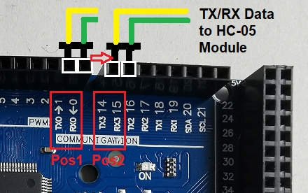
That concludes the HC-05 setup. The HC-05 data flying lead should be removed from the UART3 connector and re-connected to RXD0/TXD0:-
Reconnect these to Mega UART 3 female sockets marked TX0 and RX0. The yellow wire goes to TX0 and green to RX0. (Pos1 in the picture).
Compile and Upload the EX-CommandStation Sketch
Having assembled the CommandStation we can install the software then return here to carry out some simple tests.
Finally…
The final stage of the CommandStation build is to attach the lid using M2.3 x 8 Panhead self-tapping screws.
Attach 4 sticky feet to the base of the enclosure.
Solder your MAIN and PROGRAM track feeder cables to 5.5mm x 2.5mm DC Plugs
OR
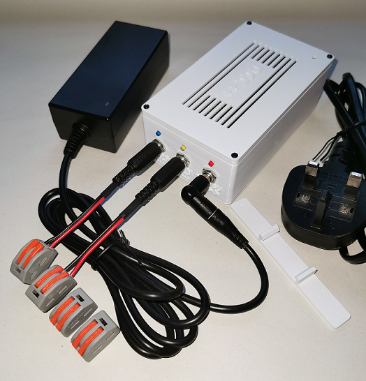
(Optionally). Make two PROGRAM and MAIN Track ‘pigtail’ cables using 5.5mm x 2.5mm DC Plugs, 100mm cable and terminate these with click release connectors so that your MAIN and PROGRAM Track cabling may be easily and quickly connected. (See picture below)
Optional Fixing Bracket
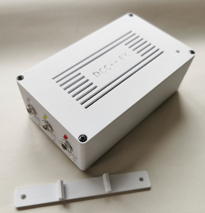
An optional fixing bracket may be attached to the underside of the enclosure. It simply clicks into place with small tabs that fit between the vents. Once the bracket is clicked into place it may be screwed to a surface with the 4 sticky feet and the bracket acting as spacers thus allowing air to circulate through the vents.
Setup of the Bluetooth Host (Windows 10) Serial COM Port
Windows 10 will communicate serially over Bluetooth via a ‘Standard Serial over Bluetooth link’. We will need to add a new COM Port for the CommandStation’s Bluetooth connection.
Check COM port devices:-
Click the Windows Start Button – Type Device Manager (to search) and click the search result ‘Device Manager’ App listed (see below screenshot). The Device Manager App opens in a new window. Click on Ports (COM & LPT) to expand.
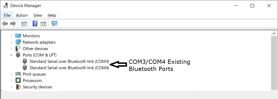
In this screenshot, there are two existing Bluetooth COM Ports. (COM3/4). (Ignore these).
Power on the EX-CommandStation. The HC-05 Bluetooth module should enter pairing mode (the HC-05 indicator red LED blinks on/off rapidly. It may be spotted through the 3D printed enclosure top grille).
Add a new Bluetooth device to Windows 10:-
Click the Windows Start Button – Type Add Bluetooth and click the search result ‘Bluetooth and other devices settings’ listed to open the Windows Bluetooth Settings App (see below screenshot).
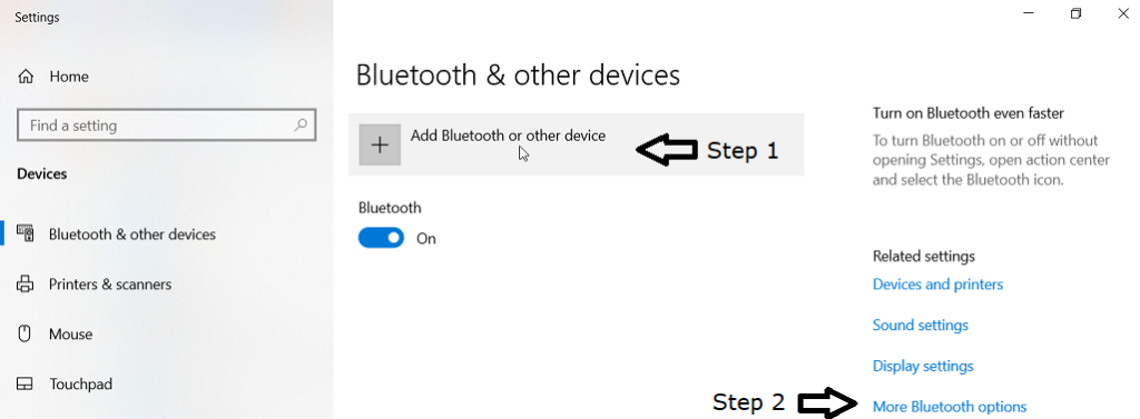
Click ‘Add Bluetooth or other device’ (Step 1 in the above screenshot).
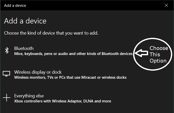
In the ‘Add a device’ window, click the Bluetooth Mice, keyboards etc entry.
(See picture)
Windows 10 will scan for Bluetooth devices that are in pairing mode.
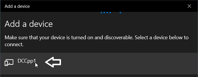
Click on discovered Bluetooth name, in this example DCCpp1
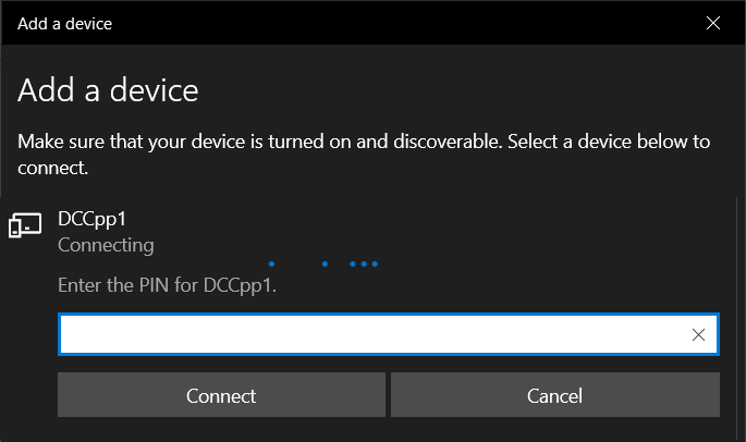
Enter the PIN number for the DCCpp1 Bluetooth device, then click ‘Connect‘
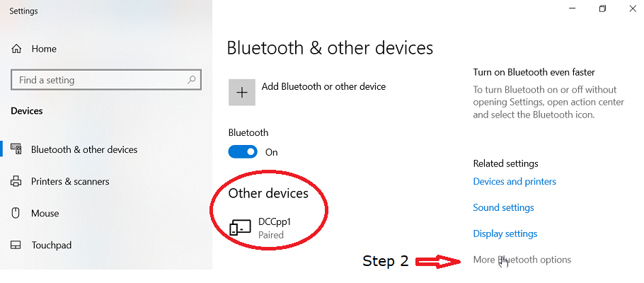
If Bluetooth pairing is successful, then device DCCpp1 should appear in the list of Bluetooth & other devices (showing status ‘Paired’) and the HC-05 Bluetooth module LED blink rate will change from rapid off/on to a slower off/on rate to indicate it has ‘Paired’
Click ‘More Bluetooth options’ to display the Bluetooth Settings box. (Step 2 in the above picture).
A new window ‘Bluetooth Settings’ is launched
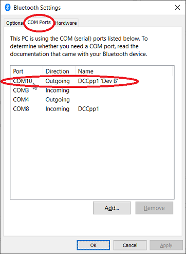
Click the COM Ports tab
Check for a new COM Port entry, (in this example COM10) showing it is an outgoing Port with the name DCCpp1 ‘Dev B’.
Make a note of the COM port as this is used later to connect to the Bluetooth serial port. In this case COM10. (Ignore the Incoming COM8 port DCCpp1).
(The name DCCpp1 relates to the name of the Bluetooth device paired with earlier).
If the name does not appear in the list with a ‘Dev B’ name, then click ‘Add’ and follow the prompts to search for the previously paired CommandStation Bluetooth device (DCCpp1 in this example).
Quick Test
We can now perform a quick test to ensure that the Bluetooth COM Port is working:-
- Power the EX-CommandStation from the mains DC Power Supply, the LED power indicator (Red) should illuminate.
- In the Arduino IDE, select the Bluetooth COM Port created in the previous steps. (In this example COM10)
- Open the Arduino Serial Monitor – the Bluetooth LED indicator should flash to indicate that a valid Bluetooth connection has been set up. It may be viewed through the vents on the top of the CS. The flash pattern is, LED flashes on twice, with the LED off for a longer period. This pattern repeats.
- From the Arduino Serial Monitor, set the Baud-rate to 115200 and select both NL and CR
- In the Serial Monitor, enter the command <1> and click Send
- The Main/Prog Track LEDs on the CommandStation should illuminate brightly
- Enter the command <0> and click Send
- The Main/Prog Track LEDs should turn off or illuminate dimly
JMRI DecoderPro settings
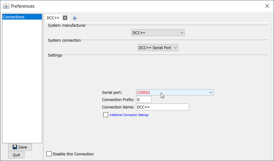
COM10 is entered as the Serial port in Preferences – Connections.
Other settings are as shown in the below picture.
Click ‘Save’ to save the CommandStation Connection options and JMRI will close and restart, attempting to connect to the Bluetooth CommandStation over a Bluetooth virtual COM port COM10.
Example Setup of the Bluetooth Host (Android) and DCCpp Cab App
The CommandStation is compatible with the Android App ‘DCCpp Cab’ from Peyuton.
Pairing it on Android devices is straightforward:-
1. Go into Android Settings
2. Tap ‘Bluetooth’ to display a list of PAIRED DEVICES and AVAILABLE DEVICES
3. Assuming the CommandStation’s HC-05 is not already paired/connected to a previous host, then if it is in pairing mode, then its Bluetooth name should be listed under AVAILABLE DEVICES.
4. Tap the entry, then enter the pairing PIN. If pairing is successful, then it will appear in the PAIRED DEVICES list.
5. Open the DCC Cab app and tap the three dots icon (top right) – tap ‘Connect BT’ to see a list of paired Bluetooth Devices. Tap the entry for the Bluetooth Controller name and the app should connect successfully.